Soldering Exercise
(In this exercise you can follow along how to solder your own PCB, power a stepper motor and connect a sensor or potentiometer!)
Preparing the motor driver
If your motor driver already has soldered headers you can skip this step!
Here is what the stepper motor controler looks like:
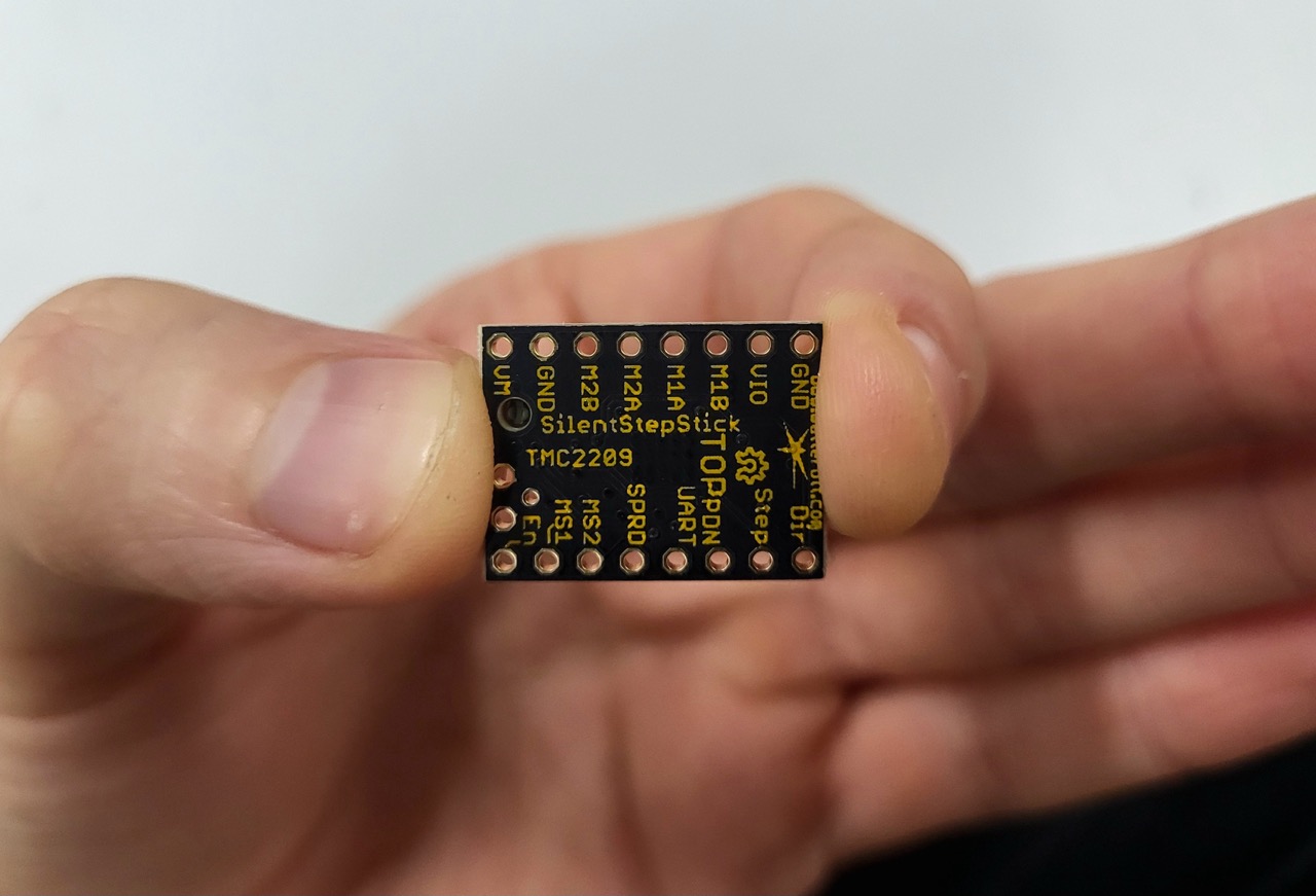
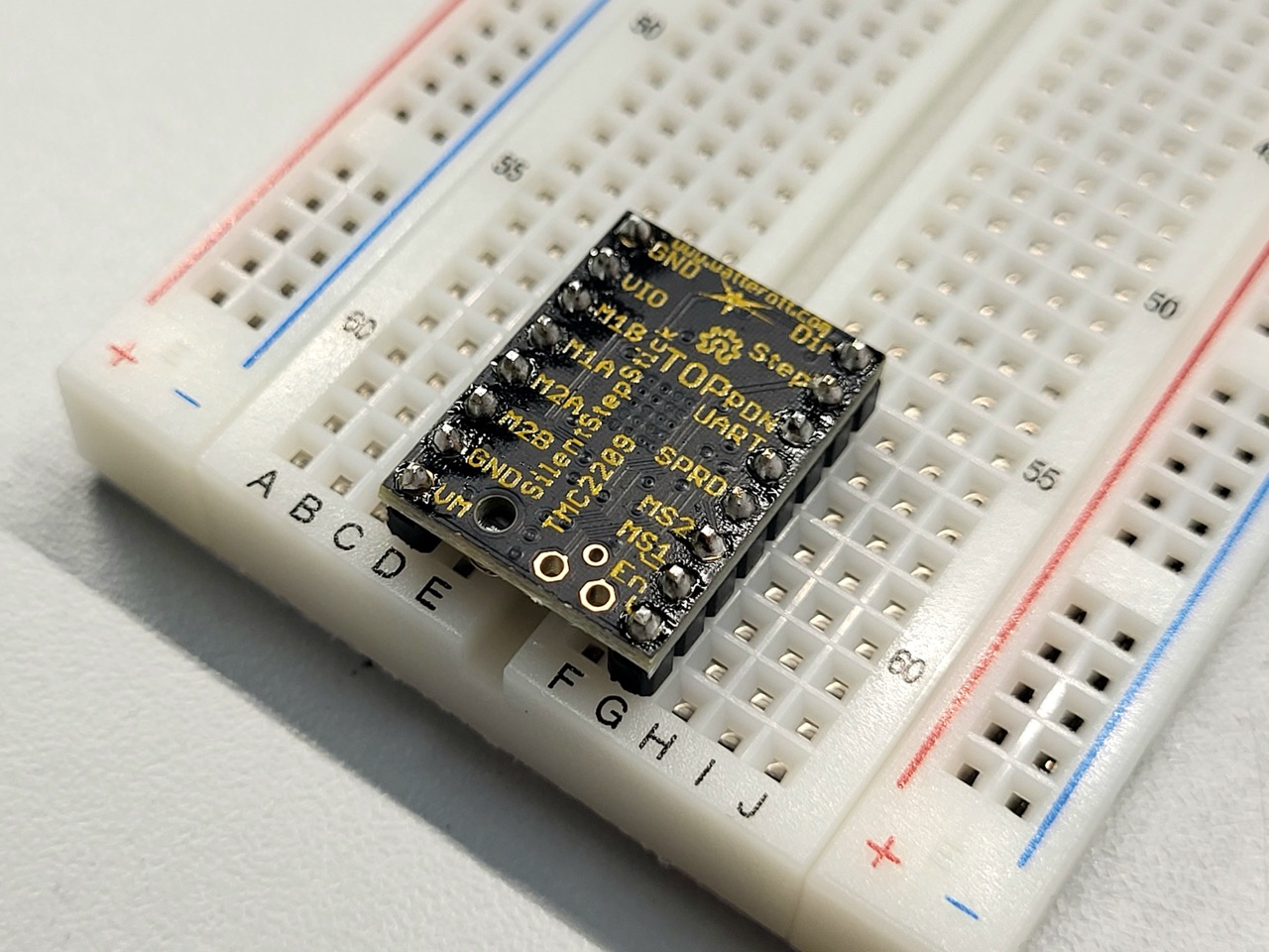
Soldering the headers of the motor driver
- Place the controler with the text facing up for easy access to the current limiter and ease of reading pin names
- Solder the outer pins first
- Then solder the rest
Gather your components
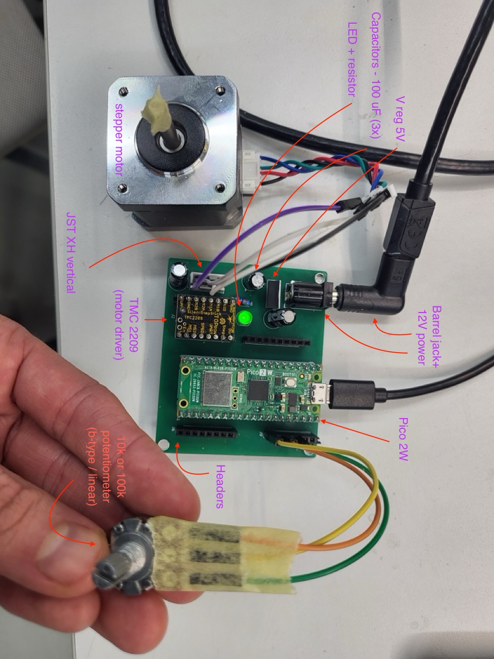
- Header sockets (cut them to lengths of: 2x20, 2x8, 1x9, 1x8, 1x7)
- 1x LED
- 1x 330R (you can calculate the actual value your LED needs, but this should be fine for most)
- 3x 100uF capacitors (rated for at least 12V!)
- 1x voltage regulator (5V version) - part number: 7805ABT
- 1x JST XH vertical 4 pin header (tht)
- 1x RP pico 2W
- 1x TMC 2209 stepper motor driver
- 1x barrel jack socket for power
- 1x 12v barrel jack (5.5mm / center positive)
- 1x potentiometer - 10k or 100k b-type linear works just fine
- You will also need a few jumper cables and maybe a breadboard depending on your setup